
Bit of a long shot I know but does anyone have circuit regulator for the Z1000 voltage regulator?
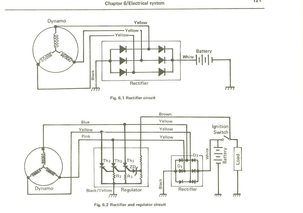
Haynes manual shows one that has 3 triacs, zener diode and 2 resistors but I a not convinced it is correct (but I need to figure out how exacty it works).
Or a similar circuit? (I plan to fit inside the origian case, easier said than done perhaps...)
I do have a commbined rectifier/regulator unit but do not want to chop up the loom just yet, especially since I do not know if the unit is working.
Hello Guest User,
Please feel free to have a look around the forum but be aware that as an unregistered guest you can't see all of it and you can't post.
To access these 'Registered Users Only' areas simply register and login.
Please feel free to have a look around the forum but be aware that as an unregistered guest you can't see all of it and you can't post.
To access these 'Registered Users Only' areas simply register and login.
circuit diagram for voltage regulator?
Moderators: KeithZ1R, chrisu, paul doran, Taffus

-
Steve Cooke
- Hardcore

- Posts: 1612
- Joined: 18th Mar 2007
- Location: Southampton
Regulator
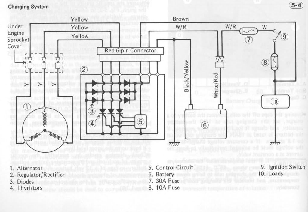
Hope these help from the kawasaki manual Z1000 A1/A2.

[img][img]http://i162.photobucket.com/albums/t263/stevencooke/DSC04691.jpg[/img]
[/img]
[img][img]http://i162.photobucket.com/albums/t263/stevencooke/DSC04692.jpg[/img]
[/img]
[img][img]http://i162.photobucket.com/albums/t263/stevencooke/DSC04691.jpg[/img]
[/img]
[img][img]http://i162.photobucket.com/albums/t263/stevencooke/DSC04692.jpg[/img]
[/img]
-
Steve Cooke
- Hardcore
- Posts: 1612
- Joined: 18th Mar 2007
- Location: Southampton
Regulator
Missed one.
[img][img]http://i162.photobucket.com/albums/t263/stevencooke/DSC04686-1.jpg[/img][/img]
[img][img]http://i162.photobucket.com/albums/t263/stevencooke/DSC04686-1.jpg[/img][/img]
Who is online
Users browsing this forum: No registered users and 17 guests