Page 1 of 2
Supercapacitor battery experiment.
Posted: Sat Jun 01, 2013 10:37 pm
Author: j.wilson
Posted: Sun Jun 02, 2013 10:32 am
Author: Jay1969
Awesome! Seen similar on YouTube, but not so neatly
packed as yours

Posted: Sun Jun 02, 2013 6:42 pm
Author: Rich
I'd make the bits of heat shrink longer and if the box is steel not plastic also think of a few Orings over the screw heads to ensure that it won't wear through the coating in time.
Posted: Sun Jun 02, 2013 9:03 pm
Author: j.wilson
You are right Rich these capacitor batteries need a lot of consideration. They discharge so powerfully they have to be handled with some care.
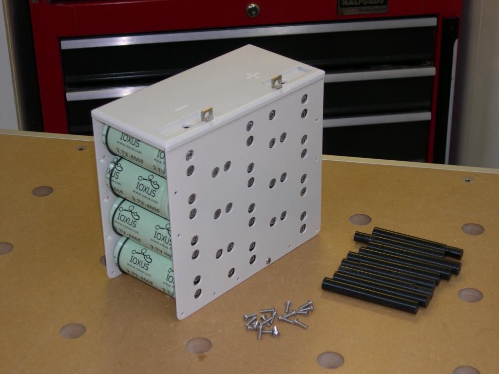
I was worried about the bolts coming undone, or something metal falling into the unit. So all the bolts are captive in some way- and whilst they could come loose- they can't fall out of their thread.
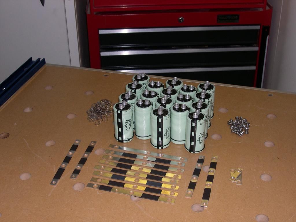
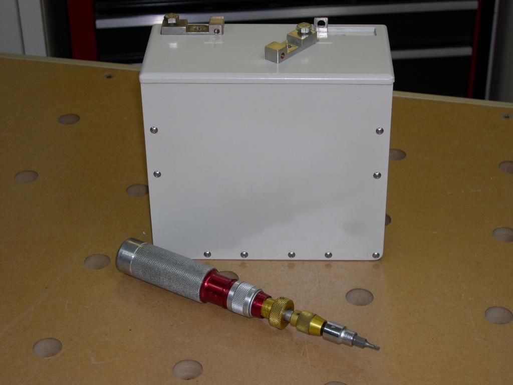
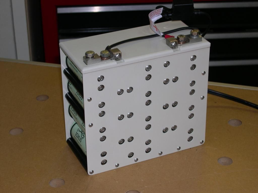
The box is made from fibreglass with a tufnol top, all the contact bits and busbars are made of copper -I tin plated them all to stop corrosion that's why they look like steel.
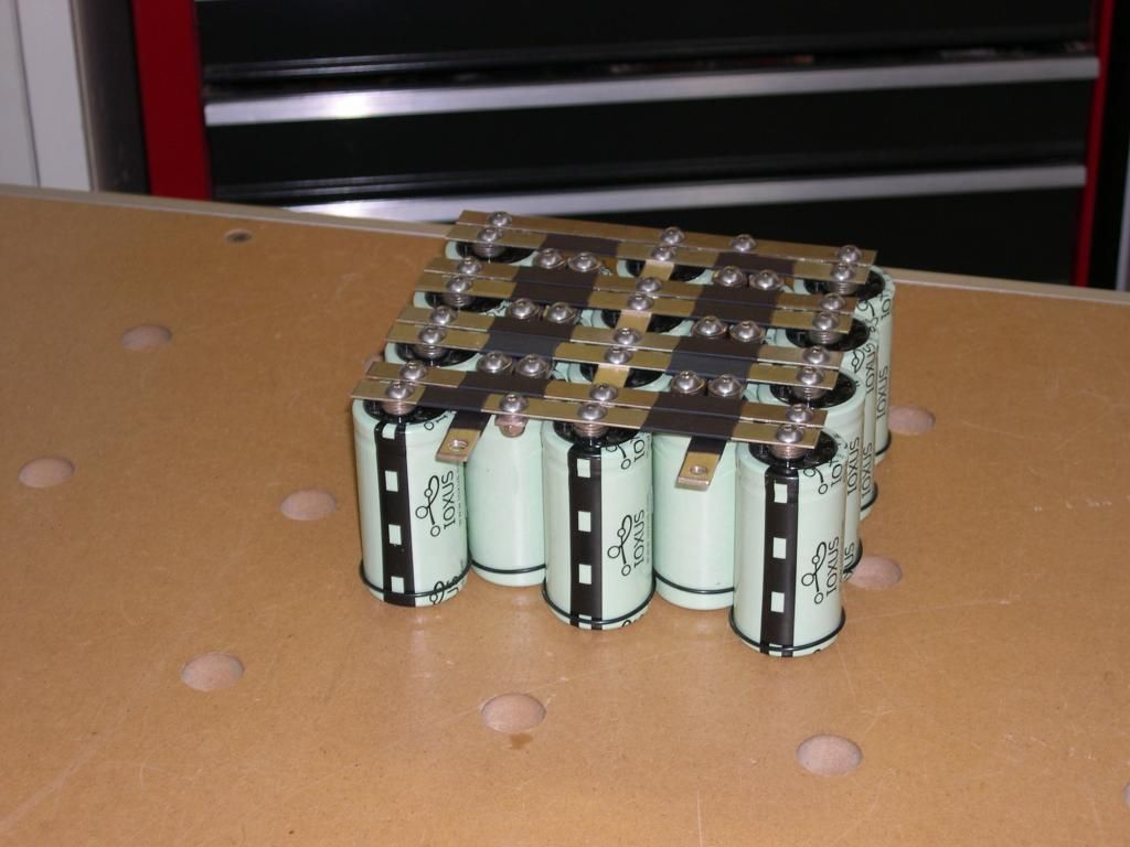
The busbars are attached to the capacitors with a little pack of washers- each of the crossing busbars is placed at different levels of the washer stacks so that they don't and can't touch because the capacitors can't move relative to each other.
The heat shrink is to stop anything from bridging the gap and is not used to prevent the busbars shorting. They are just for "belt and braces"- I feel quite nervous sitting over this battery- but so far it works as expected.
Posted: Mon Jun 03, 2013 10:07 am
Author: ruffle
That's a really neat job. Did you make the housing yourself?
What's the intended use of the bike that you're fitting this to?
Posted: Mon Jun 03, 2013 10:14 am
Author: j.wilson
yes, made all the bits myself.
Intended use?
It's a battery for my Z650 special. I use it for most things short and long runs- even go away on it, but I don't use it in the winter.
Posted: Mon Jun 03, 2013 11:14 am
Author: ruffle
I should have guessed from the 3D model

How are you going to waterproof it? Seal the whole 'battery' box?
Posted: Mon Jun 03, 2013 3:30 pm
Author: j.wilson
My battery box is pretty sealed anyway- it certainly does not get wet inside when I ride in the rain- so I'm not anticipating doing any extra waterproofing.
My view of the whole project is that at present these capacitors are pretty marginal for this use.
They have not let me down yet, but I don't feel so confident in them yet, I worry every time I leave the bike that it will start on my return. I think that the biggest problem is when the lights are on as they drain more power than the generator can supply on tickover- so in the few seconds of putting the bike away (engine on tickover and the lights on) at night the charge on the pack goes down to below 12v- and that's marginal for a start from cold.
I will keep testing to see if there is a problem or not, and I have a small mains 14v power supply if I ever get caught short- it takes about 2 mins to go from 10v to 13v.
Posted: Mon Jun 03, 2013 5:23 pm
Author: ZedHead
How are they connected up? I see some banks in parallel and others in series
Posted: Mon Jun 03, 2013 6:53 pm
Author: j.wilson
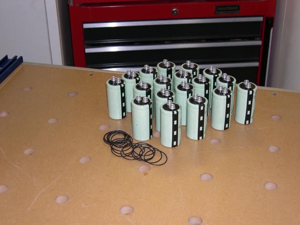
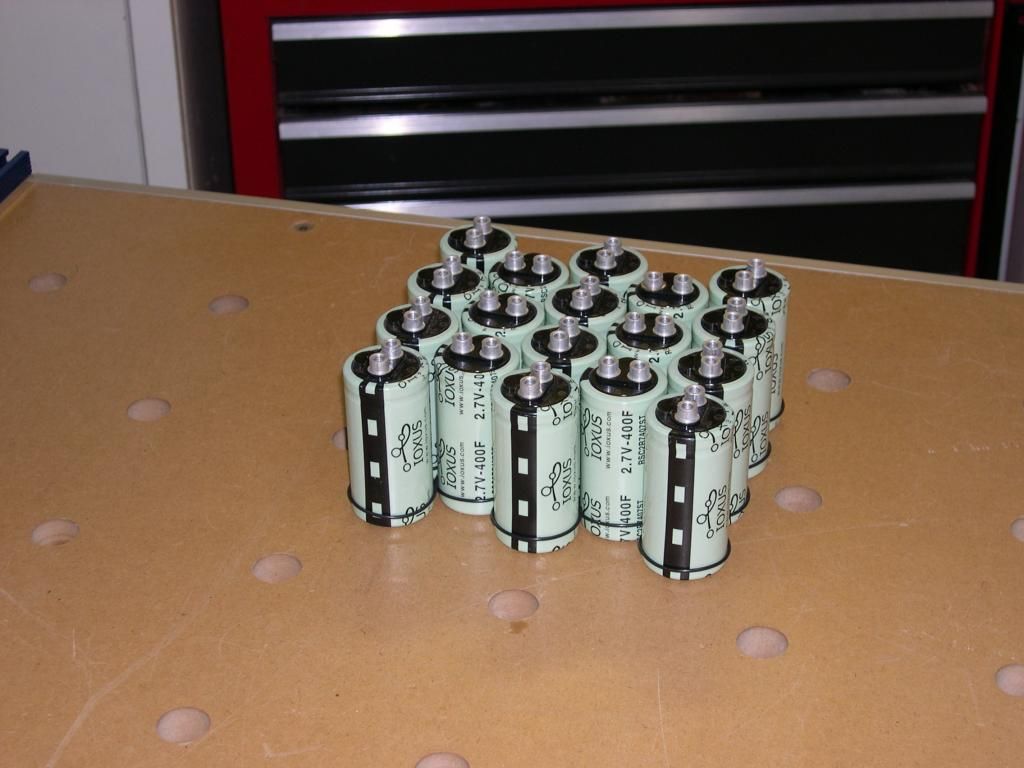
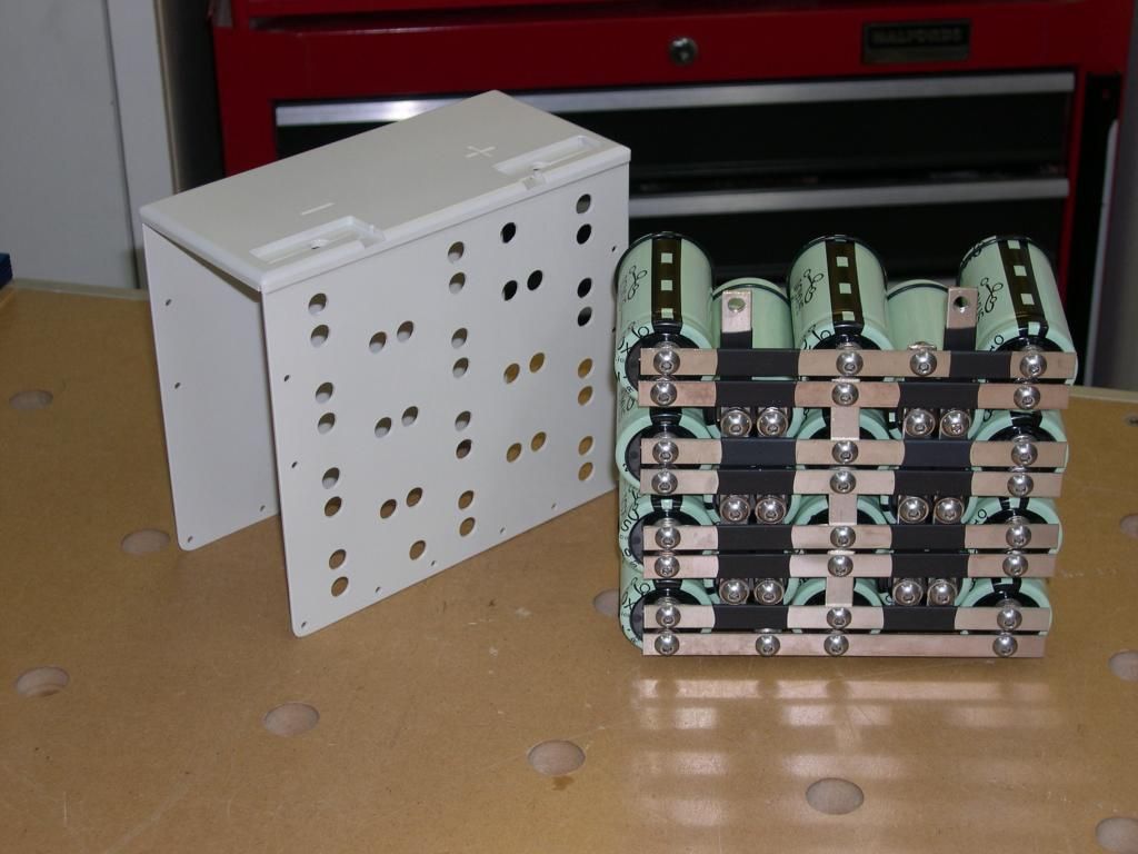
They are 2.7 v each and they must not be over charged.
So you need a series of 6 (6 x 2.7 = 16.2) to gave a max of 16.2v well over what they will see.
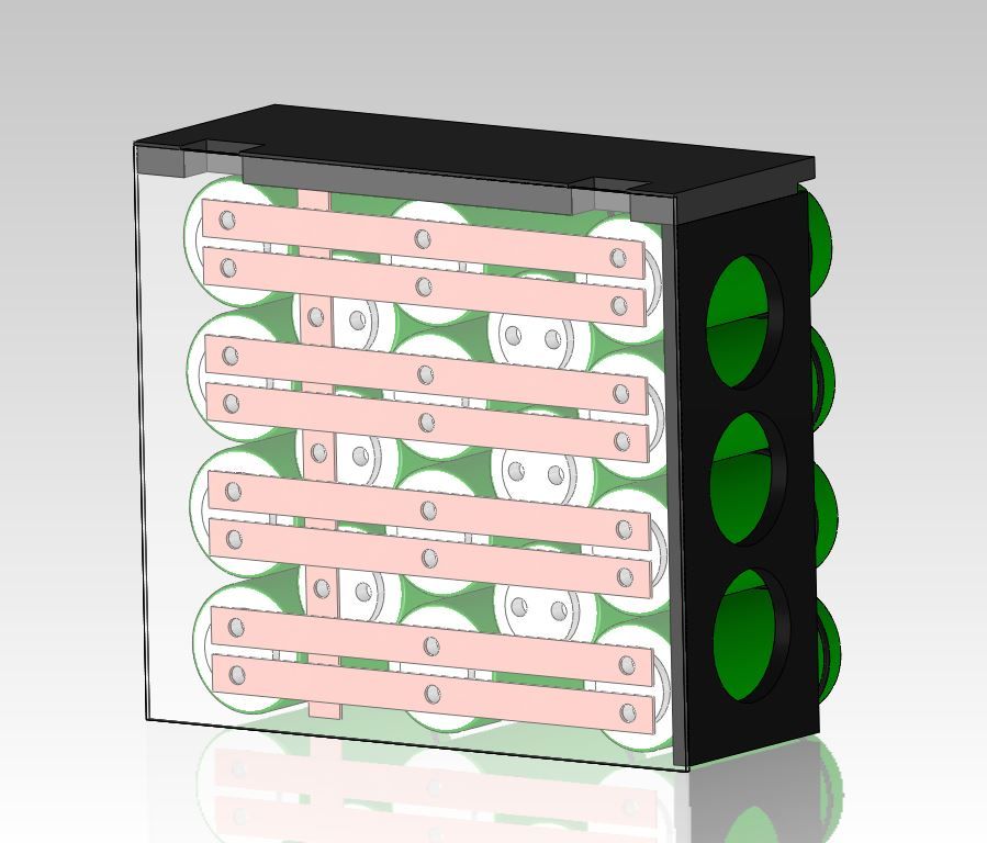
But just 6 in series doesn't provide enough capacity- so each one of the 6 are paired with another two in parallel.
So its 6 sets laid in series- and each set is 3 in parallel.
Each capacitor is 400 F so 3 in parallel gives 1200F and these arranged in a series of 6 gives a total of 200F
capacitor connection
Posted: Wed Jun 05, 2013 10:26 am
Author: buzzard
In the picture of all the caps connected with the busbars are the two vertical banks of caps connected the right way to the horizontal banks of caps, or am I missing something here? Buzzard.
Posted: Wed Jun 05, 2013 11:02 am
Author: j.wilson
HA!
No you are not missing something, I changed their polarity before I fitted them- that's the trouble with assembling something to photograph- its a bit distracting!
The horizontal rows of 3 caps are all paralleled together, and the two vertical columns are paralleled together. These triples are then connected together in series attaching positive to negative to combine their voltage.
Now further to my experiments.
Hmmmm, I have run into a bit of a problem- at night with the lights on (obviously that also includes all the stuff like fuel injection and fuel pump) the whole load is enough to drag the generator down to 11v- especially when dribbling around town at 1500rpm.
I'm not sure if there is a problem with my generator or if its normal output drops off a lot from its rated 20amps at 5000rpm as the rpm drops lower.
Lights and fuel pump will use 11amps on their own.
Humph!
Re: capacitor connection
Posted: Wed Jun 05, 2013 1:50 pm
Author: ZedHead
buzzard wrote:In the picture of all the caps connected with the busbars are the two vertical banks of caps connected the right way to the horizontal banks of caps, or am I missing something here? Buzzard.
Well spotted! Not called buzzard for nothing ... perhaps it should be eagle eye

Posted: Wed Jun 05, 2013 2:05 pm
Author: j.wilson
Anyone know of an upgrade the alternator?
Electrex do a replacement- but I don't know if it is any more powerful.
Without the lights on the system copes- note here that I have an ECU, fuel pump and heated lambda sensor that all add to the load.
My rear light is LED so I guess that the load I see pushing the system over the edge is about 6amps.
Clearly this is a problem for my battery too- it would just take longer to show up before it is flat. Perhaps this explains the problems I've been having with the battery too.
At the moment it feels a bit like Apollo 13 trying to manage the current.
I don't use the heated lambda for closed loop so I could disconnect it, and I can buy a HUGELY expensive LED headlight that draws only 2 amps.
hmmm.
Posted: Wed Jun 05, 2013 4:11 pm
Author: Rich
Have you looked into the newer Mosfet RRs?