Hello Guest User,

Please feel free to have a look around the forum but be aware that as an unregistered guest you can't see all of it and you can't post.

To access these 'Registered Users Only' areas simply register and login.

Z650/old school triumph/Z1100 Chimera.

Work in Progress

Moderators: KeithZ1R, chrisu, paul doran, Taffus

Message
Author
Rich
Hardcore
Hardcore
Posts: 2835
Joined: 4th Mar 2003

#16 PostAuthor: Rich » Wed Oct 26, 2011 5:20 pm

j.wilson wrote:yea, but disposing of the body is ALWAYS the biggest problem.

Sausages :D
Rich
diplomacy is a form of art - I was never any good at art

User avatar
tlc
International Rep
Posts: 5239
Joined: 6th Nov 2007
Location: Aylesbury

#17 PostAuthor: tlc » Wed Oct 26, 2011 6:30 pm

Yeah, inspirational thread this.

Wasn`t it your shed that was so interesting as well ?
Asphalt Cowboy

Phil Churchett award winner 2015

User avatar
firyembers
Custard Creem
Posts: 223
Joined: 11th Jun 2011
Location: Back And Loving Life In Cardiff

#18 PostAuthor: firyembers » Sun Oct 30, 2011 7:28 pm

Hi Julian
Nice to see you putting it back up on here...
The build inspired to get the bits to convert my motor to Fuel Injection and thus one of these days will put it back up on here.
Have fun..
Regards Grahame
Life shouldn't be a journey to the grave with the intention of arriving safely in a well-preserved body, but rather to skid in sideways, cigar in one hand, beer in the other, body used up, totally worn-out and screaming, "WOO HOO, what a ride!"

User avatar
j.wilson
100Club
100Club
Posts: 229
Joined: 23rd Jul 2011
Location: wimborne

#19 PostAuthor: j.wilson » Thu Dec 08, 2011 11:58 am

Here is the shed info
http://z1ownersclub.co.uk/forum/viewtop ... sc&start=0


I decided to go with fuel injection. Primarily because I wanted to keep the controls light, I didn’t want to go with CV carbs and flat slides can make the throttle stiff. On reflection perhaps there is a late model CV carb that could do the trick.
For the FI I went for Hayabusa throttle bodies. They were not an ideal choice- more of a mistake really.
To make them fit required quite a bit of work. First the spacing had to be changed, the gap in the middle widened and the gap between the outside ones shrunk- and of course the throttle action had to move to the centre rather than the end. In the process I also put in a second fuel connection to allow the fuel to flow in and out. I wasn’t happy with the injectors either so I fitted some alternatives- sized for the engine.
Throttle bodies in bits.
Image
Part assembled
Image
And fully assembled.
I made a little cap to go over the end of the throttle rod to make it all neat, painted it and glued it on.
Image
Lastly I needed a little fast idle plunger. Bad picture but you get the drift.
Image
All this adjustment of the throttle bodies left the inlets and the ports miss-aligned by a few mm here and there, so I had to make new port adapters to line them all up perfectly.
These adapters were made of aluminium and turned on my trusty Chinese lathe, however they took ages and were the most complicated things I have ever turned. First the outside had undercuts where the bolt heads fit on the flanges. Second the throttle body dia and the port dia are different so the thru hole in the adapters are tapered to match the dia at each end, next these thru holes were angled to the side to match the spacing and finally angled upwards so that the throttle body has more space underneath so I could fit in the pressure regulator underneath. Lots of head aches, but the result all fitted together nicely and solved many problems in one go.
Image
Fitted using silicone tubes and stainless jubilee clips.
Image
It didn’t go all to plan. The rear of the throttle body is unsupported as I just fitted K&N filters. As a result over time they “sagâ€￾ down at the rear- slowly slipping out of the inlet rubbers. So I made a little stay that fits under the throttle body with a rubber foot that supports it nicely.
Image
All in all the installation looks neat and is quite easy to fit and remove.
Last edited by j.wilson on Wed Mar 27, 2013 10:32 pm, edited 1 time in total.
z650/1400 bonneville hybrid.

User avatar
j.wilson
100Club
100Club
Posts: 229
Joined: 23rd Jul 2011
Location: wimborne

#20 PostAuthor: j.wilson » Thu Dec 08, 2011 12:17 pm

I thought I’d take a moment to show how I made all the brackets for the bike. I use a simple CAD package to help.
So, for the brake calliper hangers:
First I offered the calliper up to the fork leg and disc. With it in place I made a sketch of the critical bracket dimensions.
Image
I transferred these dimensions to the CAD system and joined the mounts up with the body of the bracket.
Image
I printed this drawing out and used double sided tape to stick it to a piece of card. Then with scissors I cut it out. To make the mount holes (or any tight detail) I used a leather punch to nibble out the card.
Image
With it finished I actually fitted it to the bike and hung the callipers on it.
Image
Of course it didn’t go right first time, so I repeated the process twice till I was happy.
Finally I created a drawing for the real calliper brackets and had them CNC machined. All fitted then first time with a nice gap between the disc edge and spaced so the disc falls in the centre of the gap in the callipers.
Image
This is how I made all the brackets, it was surprising how strong the cardboard mock ups were.
z650/1400 bonneville hybrid.

User avatar
j.wilson
100Club
100Club
Posts: 229
Joined: 23rd Jul 2011
Location: wimborne

#21 PostAuthor: j.wilson » Thu Dec 08, 2011 12:44 pm

Image

Image

I used the same technique to make a little idiot light display. This time I used a bit more sophisticated CAD system- a 3D system. This allowed me to display (and rotate) a 3 dimensional model of – not just the part- but the assembly of all the parts involved.
The mock up
Image

The computer model of the part.
Image
The whole assembly
Image
Exploded you can see how it all fits together
Image
The circuit board was designed so that its components nested into the aluminium chassis, cut-aways were used to accommodate the electrical components. I could make the assembly transparent (like an x-ray) so I could be sure it all lined up ok.
Image
I made a drawing of the circuit board and sent it off to a prototype manufacturer to make me one, plus a spacer on the rear to keep it insulated.
Image
With the bits in, I chopped the indicators down so they fitted into the assembly. I soldered on surface mount type high brightness white LEDs and resistors so they could run on 12-14vdc, finally the cables were designed to knot when they went thru the pcb to retain them and strain relieve the joints (a little RTV was used).
Image
Image
Image
Image
Image
The whole assembly fitted to the bike as designed, looked neat and worked a treat. The only problem I had was that the indicator idiot light needed a bulb fitted in the circuit to give a load to make the flash rate right.
z650/1400 bonneville hybrid.

User avatar
j.wilson
100Club
100Club
Posts: 229
Joined: 23rd Jul 2011
Location: wimborne

#22 PostAuthor: j.wilson » Thu Dec 08, 2011 12:58 pm

Image
Fibreglass rear mudguard, painted white. Fitted with bullet indicators and an LED tail light. The light was chosen to illuminate the number plate too. I fitted the loom on the underside and used soft ali tabs to retain the loom.
Image
Image
Image
I made a chain guard from a piece of 3mm ali angle that I just jig-sawed, hole sawed and then bent the end into an arch. I glued a little ali angle strength piece where the shock cut-out was to prevent it breaking off and painted it all black.
Image
z650/1400 bonneville hybrid.

User avatar
j.wilson
100Club
100Club
Posts: 229
Joined: 23rd Jul 2011
Location: wimborne

#23 PostAuthor: j.wilson » Thu Dec 08, 2011 1:14 pm

What else to say?
I put a tap on the hydraulic clutch line so I could switch it off when I took the engine case off- otherwise the piston could pop out.
Image
I rewired the whole bike using stuff from VWP. I was happy to do this to get rid of the 30 year old wires, plus I wanted to change the loom design a little and some function. I made the FI loom entirely separate so I didn’t get confused. I had to modify the ignition switch and the handle bar switches to make it all function the way I wanted (so that for example if the lighting fuse blows it does not stop the motor).
It was a bit of a squeeze in the little Harley sportster headlight.
Also note I used velcro as cable ties, I prefer this as it is easy to make and break as well as having no sharp edges and easy to get in long lenghts.
Image
I used PVC sleeving, with little bits of adhesive lined heat-shrink for the joints and ends. I fitted water proof connectors where ever the joints were exposed, otherwise I used conventional spade block terminals.
A really important thing here is keep a good record of the design- I went to the trouble of drawing a new wiring diagram.
Image
This also included the FI bit.
Image
z650/1400 bonneville hybrid.

Crofty
ZedHead
ZedHead
Posts: 1150
Joined: 18th Nov 2009
Location: York

#24 PostAuthor: Crofty » Thu Dec 08, 2011 1:28 pm

Bloody great, like the idea of the tap on the clutch line. Projects like this can only inspire people to do more. Crofty

User avatar
j.wilson
100Club
100Club
Posts: 229
Joined: 23rd Jul 2011
Location: wimborne

#25 PostAuthor: j.wilson » Thu Dec 08, 2011 5:54 pm

On the end of the crank Ray Debben had made a rotor to trigger the ECU.
Image
I made a sticker so that the various trigger points could be understood easily (so I could strobe the timing without confusion).
With everything wired in and checked I loaded the software onto the laptop and connected it to the ECU.
Image
Image
Image
After a little fiddling to get the laptop comms settings right, the ECU and the laptop talked to one another.
The great thing about the software is that it gives a dashboard that shows all the sensor readings.
Image
There is also a setup screen that lets you configure the system to the sensors and the engine config that you have. Some of these are obvious, some are standard settings.
The software comes with a list of standard maps, I chose one for a Suzuki that with a little fiddling looked ok to make a start.
The system also has an oscilloscope function that allows you to see the signals from the crank sensor. Every time you start the engine the ECU has to understand where the engine is on its cycle and fire the sparks and fuel accordingly. The oscilloscope trace allows you to see what the ECU sees from the crank sensor- if there is any problem (false triggering etc) then the ECU does not configure and the fuel and sparks don’t happen.
This is the display trace.
Image
I had a lot of problems here, but eventually got a good enough signal for the sparks to switch on.
Pressed the start button with the fuel pump fuse in place and the motor just cranked and cranked.
I fiddled with the cold enrichment and with a sudden roar the engine sprang into life.
Promptly stopped, but it was alive.
Then its back to the set-up screens and look for problems-
Image
Otherwise its looking at the fuelling/ignition tables.
Image
With more fuel I got the engine running for a few minutes to do two things, first I checked the ignition timing with a strobe and second I “balanced the carbsâ€￾.
Image
There are several ways to add more fuel for example. Cranking enrichment, cold engine enrichment and adding fuel to the main fuel map. As you get more familiar with the systems so you get more able to identify which table to fiddle with.
After several sessions the bike ran, but quite rough, and started intermittently.
One word of warning when considering FI- whenever something went wrong I found it easy to get bogged down in my naivety, seeing shadows of complicated problems when often the problem was basic and nothing to do with the FI.
So, having got frustrated and stuck I asked Ray Debben for some help. He started by checking the ignition timing, and found his strobe did not trigger very well. I was not so familiar with strobe so I hadn’t really noticed the problem.
At least now I had a problem to investigate.
I purchased one of those Gunsen ignition testers- great to check the power of sparks.

Image

This tool revealed that the sparks were terribly weak. First problem was my old plug leads were leaking sparks around the place (where they touched the engine cases), second was that the standard signal that the ECU was sending to the coils was not enough to give a beefy spark- so with a simple adjustment of the set up table (but outside the recommended range) the coils were delivering strong sparks. But still they were irregular at tick over.
After looking at the oscilloscope trace and the error codes- it was clear that the crank sensor was not delivering the goods. After some research I found that the crank sensor I was using was an induction type. This means that it is a little magnet on a metal bar with a coil around it. The magnet creates a magnetic field and as the metal teeth of the timing rotor pass the sensor the field is distorted and induces a pulse in the coil- and where there is a gap in the teeth there is a clear null period to trigger the ECU.
The problem is that the electrical pulses induced in the coil are dependent on the speed of the passing tooth, its distance from the sensor, the size of the gaps between the teeth and the metal mass of the tooth itself. Clearly with a production set up the system can be tailored to ensure the signal is reliable in all conditions, my set-up however was marginal and did not produce a very reliable signal at low rpm. To get over this I found a Hall effect sensor with the right characteristics. The signal it generates is very clean and is not speed dependent- I just had to provide power to it.
Here is the new sensor in position.

Image
At last, the bike started reliably and ticked over smoothly.
Last edited by j.wilson on Sun Dec 11, 2011 5:30 am, edited 1 time in total.
z650/1400 bonneville hybrid.

Padders
Hardcore
Hardcore
Posts: 4875
Joined: 15th Jan 2006
Location: Grimsby Lincolnshire

#26 PostAuthor: Padders » Thu Dec 08, 2011 6:01 pm

Excellent build nice t see the post back on the site

User avatar
j.wilson
100Club
100Club
Posts: 229
Joined: 23rd Jul 2011
Location: wimborne

#27 PostAuthor: j.wilson » Thu Dec 08, 2011 6:03 pm

I could then start fiddling with the fuel map so that it suited the engine more.
The table of numbers can be displayed as a graph so that the trends can be seen easily. A bit of a before and after shot here, I started with the smooth map and ended with a bumpy one.

Image

After a while I got to the point where the bike would start and run ok, although there was a bit of a misfire- still the fuelling was not quite right.
I took the bike up to PDQ who had a rolling road that could load the bike at all speeds. Thus we were able to map the fuelling much better than I could do by ear.

Up at PDQ

Image

The power figure- ignore the misfire.
Image

So, 126hp at the rear wheel. Not bad for a bike that weighs just about 205kg now.
z650/1400 bonneville hybrid.

User avatar
popsA1
100Club
100Club
Posts: 105
Joined: 7th Jun 2009
Location: Leamington Spa

#28 PostAuthor: popsA1 » Thu Dec 08, 2011 9:14 pm

Great to see this back Julian. Excellent engineering you’ve done and FI has got to be the way forward.
A2 1979-80. A1 1980-now

User avatar
andyb1962
Hardcore
Hardcore
Posts: 1777
Joined: 23rd Sep 2011
Location: Sheffield/Rotherham South yorks

#29 PostAuthor: andyb1962 » Thu Dec 08, 2011 10:45 pm

what a absolute quality job.
awesome planning attention to detail and great engineering.
VERY IMPRESSIVE :clap
Andy :wink:


"The greatest trick the devil ever pulled was convincing the world he didnt exist"

Rich
Hardcore
Hardcore
Posts: 2835
Joined: 4th Mar 2003

#30 PostAuthor: Rich » Fri Dec 09, 2011 8:33 am

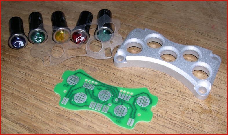
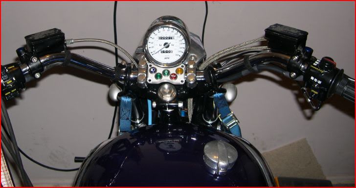
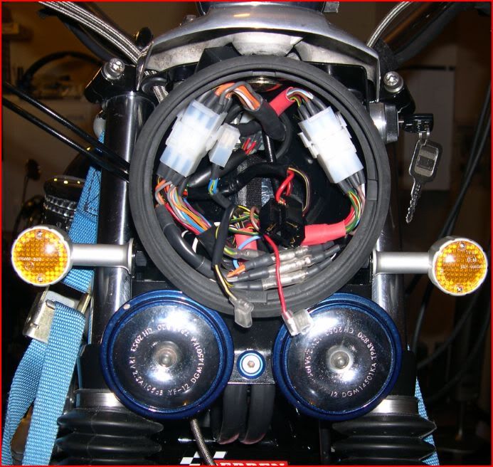
j.wilson wrote: The only problem I had was that the indicator idiot light needed a bulb fitted in the circuit to give a load to make the flash rate right.


I have mine set up for LED idiot lights but don't need the bulb, try a car flasher unit
Rich
diplomacy is a form of art - I was never any good at art


Return to “Projects”

Who is online

Users browsing this forum: No registered users and 8 guests