circuit diagram for voltage regulator?
Posted: Tue Sep 16, 2008 8:42 am
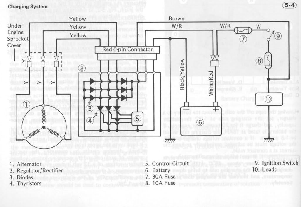
Bit of a long shot I know but does anyone have circuit regulator for the Z1000 voltage regulator?
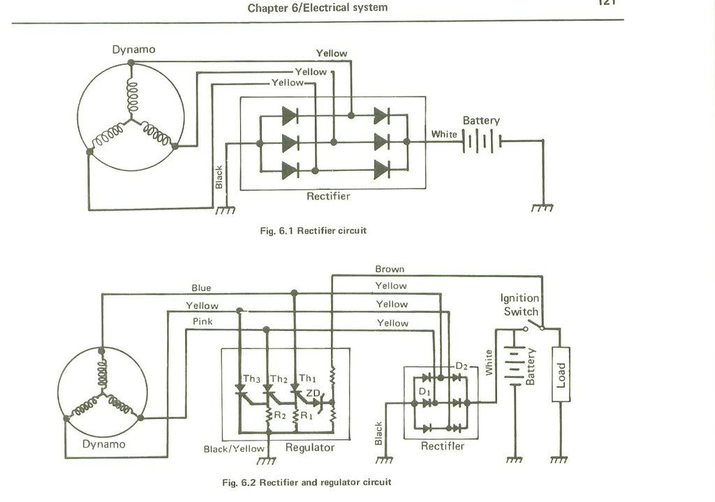
Haynes manual shows one that has 3 triacs, zener diode and 2 resistors but I a not convinced it is correct (but I need to figure out how exacty it works).
Or a similar circuit? (I plan to fit inside the origian case, easier said than done perhaps...)
I do have a commbined rectifier/regulator unit but do not want to chop up the loom just yet, especially since I do not know if the unit is working.