Hello Guest User,

Please feel free to have a look around the forum but be aware that as an unregistered guest you can't see all of it and you can't post.

To access these 'Registered Users Only' areas simply register and login.

Fitting a Dyna S ignition system - with pictures

Need help restoring, building, or finding then try here.

Moderators: KeithZ1R, chrisu, paul doran, Taffus

Message
Author
User avatar
chrisu
Moderator
Posts: 4367
Joined: 3rd Sep 2005
Location: herts

Fitting a Dyna S ignition system - with pictures

#1 PostAuthor: chrisu » Wed Sep 12, 2007 5:26 pm

As per request here is a photo guide to installing a dyna s ignition system. It assumes you have the instructions provided with the dyna system. If you don't this will not help too much.

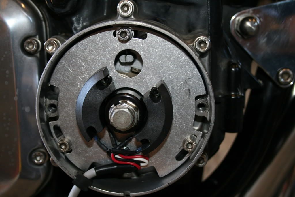
Firstly here are some shots of the points ignition system. These were taken in case I had to revert back to points.

Image
Image
Image


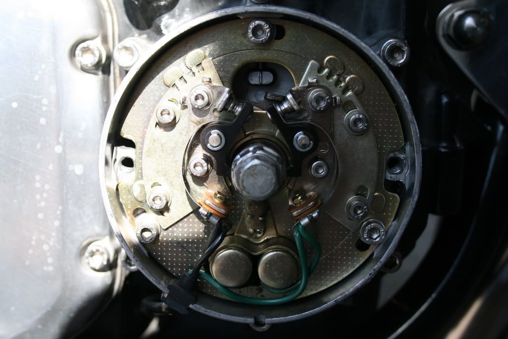
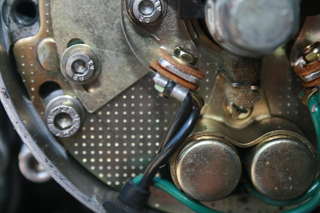
Next is the the wiring which goes from the points to the coils - these are the two wires you are going to remove/disconnect when you remove the points plate.

Image

Remove the points plate and the wires. Place is a box.

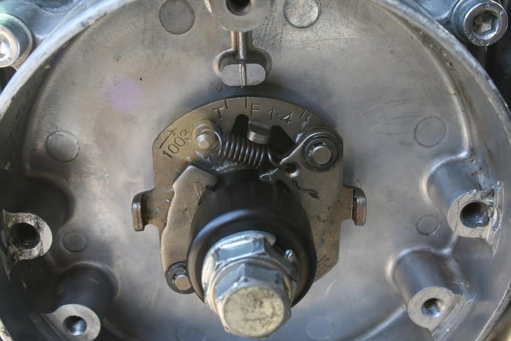
Remove the advance/retard unit - remove the points cam from it and replace it with the black trigger cam provided with the dyna system. Note this has to go on with the 1/4 makings to the top and the magnet (in the black trigger cam) to the left.

Image

Reinstall the advance/retard unit.

Mount the new timing plate and feed the wires through to where you disconnected the points wires from. It is long enough (just).

Image

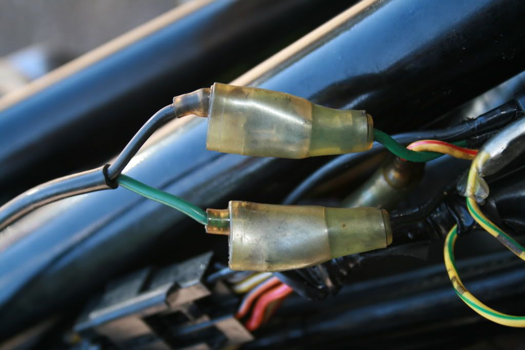
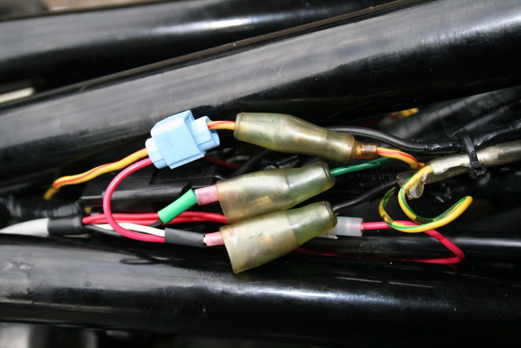
Connect the wires as shown - note mine has a white wire with a black sleeve and a black wire with a green sleeve. Use the sleeves as indicators as to where to connect to.
Crimplock the dual red wires to the red/yellow wire shown - this is the 12v power wire and give power to the triggers.

Image

Now to timing. You can follow the instructions in the manual and as provided in other threads or you can do it the way I did it. I take no responsibility for my way but it does assume you have a strobe timing light - if not follow the published procedure.

Timing

I had removed all the plugs from the engine and but had the plugs in the plug caps. slowly rotate the engine until the no 4 plug sparks. Note where the timing mark on the case is in relation to the F 1/4 mark on the advance retard unit. Adjust and repeat as necessary until they line up as the plug sparks.

I then put some tippex on the fully advance mark - about 1/2 inch to the right of the F mark. See photo.

Image

Connect everything up and it will (should) run. warm up and using a strobe check timing at over 2,500rpm. if the white tippex mark lines up you're done. If not adjust until it is.

My now starts better, runs better and idles nicely at 800rpm - never did before.

Thanks to Mr Saunders for prompt delivery of the above bit of kit.


I await all the corrections...............

User avatar
uk kev
Hardcore
Hardcore
Posts: 1531
Joined: 13th Aug 2006
Location: Berkshire

#2 PostAuthor: uk kev » Wed Sep 12, 2007 6:51 pm

Nicely done Chris.

These need putting in a seperate Tech section.

Padders
Hardcore
Hardcore
Posts: 4875
Joined: 15th Jan 2006
Location: Grimsby Lincolnshire

#3 PostAuthor: Padders » Wed Sep 12, 2007 9:10 pm

Thanks Chris

User avatar
ROZZER
Custard Cream
Custard Cream
Posts: 663
Joined: 17th Sep 2006
Location: Workington, Cumbria, UK

#4 PostAuthor: ROZZER » Mon Sep 17, 2007 6:58 pm

Spot on Chris, fitted this system to my zed last year and its the single best mod anyone can make to the motor. Much better running at all revs and idles far better than with points. Fit it, forget it.
AKA John Roscoe. PUM #028
1975 Z1B, 2013 Z800

User avatar
mothra
100Club
100Club
Posts: 139
Joined: 31st Jul 2008
Location: Reading, Berks

#5 PostAuthor: mothra » Wed Feb 18, 2009 3:41 pm

Gents, this topic is very helpful, but unfortunately is not quite low level enough for a moron like me. Chris mentions calmly in his text 'remove the points cam from it and replace it with the black trigger cam' - how the merry hell do I get the points cam out from the advance/retard plate? Do I have to disassemble the springs and circlips then reassemble or do I just hit it really hard with a hammer?

I'm trying to fit dyna-S to my z650 from a kit supplied by Jeff at Z1, and the instructions provided really aren't very helpful...

:evil:

Stu
Currently restoring a 78 z650

User avatar
mothra
100Club
100Club
Posts: 139
Joined: 31st Jul 2008
Location: Reading, Berks

#6 PostAuthor: mothra » Wed Feb 18, 2009 5:29 pm

Aha. Worked it out - for anyone else searching on 'points cam' in the future, grab the weights, pull them out as far as you can, while holding them grab the shaft and twist to the right then pull towards you. Nasty crack, then it comes right off...

HTH

Stu
Currently restoring a 78 z650

User avatar
Al
Hardcore
Hardcore
Posts: 2233
Joined: 21st Oct 2007
Location: Farnbronx Sin City N.E. Hants

#7 PostAuthor: Al » Wed Feb 18, 2009 5:44 pm

http://www.dynaonline.com/skins/downloads/Default.aspx


Good work Chris. Original instructions available for download at the above address.


AL

nanno
100Club
100Club
Posts: 375
Joined: 17th Jan 2008

#8 PostAuthor: nanno » Sat Mar 07, 2009 2:56 pm

Just one thing, I just fitted my dyna-s to my Zed yesterday night.

Please crimp yourself a proper cable instead of using this blue-thing...

It is just a matter of time, when they get less tight and you have ignition-probs...

Just my 2 cents.
Greg

P.S.: I'll post pics later.
There's no replacement for displacement!

User avatar
mick znone
Hardcore
Hardcore
Posts: 6880
Joined: 13th Jun 2008
Location: Cornwall

#9 PostAuthor: mick znone » Sat Mar 07, 2009 5:47 pm

that helps me, thanks nanno :D
I DONT CARE, IN OR OUT BUT IM ENJOYING THE DEBATE......................ARMSTRONG MT500. a pushbike, waves.....addict, no offence

User avatar
chrisu
Moderator
Posts: 4367
Joined: 3rd Sep 2005
Location: herts

#10 PostAuthor: chrisu » Sat Mar 07, 2009 5:49 pm

nanno wrote:Just one thing, I just fitted my dyna-s to my Zed yesterday night.

Please crimp yourself a proper cable instead of using this blue-thing...

It is just a matter of time, when they get less tight and you have ignition-probs...

Just my 2 cents.
Greg

P.S.: I'll post pics later.


have done since this picture was taken......... :)

cra-z1

#11 PostAuthor: cra-z1 » Sun Mar 08, 2009 6:32 pm

Better yet, use a relay to power the system. Will prevent possible voltage drops across the ignition switch or kill switch
Image

User avatar
KWACKERZ1
Hardcore
Hardcore
Posts: 1729
Joined: 1st Sep 2007
Location: Leicestershire

relay spec

#12 PostAuthor: KWACKERZ1 » Sun Mar 08, 2009 7:38 pm

I like the way that relay mod is done, what part number or spec of relay did you use as I would like to do that with mine.
Cheers
Phil

Rich
Hardcore
Hardcore
Posts: 2835
Joined: 4th Mar 2003

#13 PostAuthor: Rich » Sun Mar 08, 2009 8:11 pm

http://www.vehicle-wiring-products.eu/V ... /r20bd.jpg

Something like that by the looks of it, any 12V relay capable of handling 10A should do the job.
Last edited by Rich on Sun Mar 08, 2009 8:14 pm, edited 1 time in total.
Rich
diplomacy is a form of art - I was never any good at art

User avatar
Pigford
Hardcore
Hardcore
Posts: 13314
Joined: 2nd Jan 2006
Location: North Dorset

#14 PostAuthor: Pigford » Sun Mar 08, 2009 8:14 pm

Some clever sod on here was on about fitting a diode in line when you use a relay :?: to stop voltage irregularities (or sumink) :!:

Can't remember who/what/why/when, but seemed to have some logic behind it :shock:
And on the 7th day... Zeds were created!

Rich
Hardcore
Hardcore
Posts: 2835
Joined: 4th Mar 2003

#15 PostAuthor: Rich » Sun Mar 08, 2009 8:15 pm

It's voltage spike from the field collapsing.
Rich
diplomacy is a form of art - I was never any good at art


Return to “Bike Help”

Who is online

Users browsing this forum: No registered users and 14 guests