Hello Guest User,

Please feel free to have a look around the forum but be aware that as an unregistered guest you can't see all of it and you can't post.

To access these 'Registered Users Only' areas simply register and login.

Custom Loom ELECTRICAL ADVICE

Need help restoring, building, or finding then try here.

Moderators: KeithZ1R, chrisu, paul doran, Taffus

Message
Author
Royalratch
100Club
100Club
Posts: 366
Joined: 3rd Jul 2009
Location: London

Custom Loom ELECTRICAL ADVICE

#1 PostAuthor: Royalratch » Tue Dec 13, 2011 2:22 pm

Calling on the sparky types here.

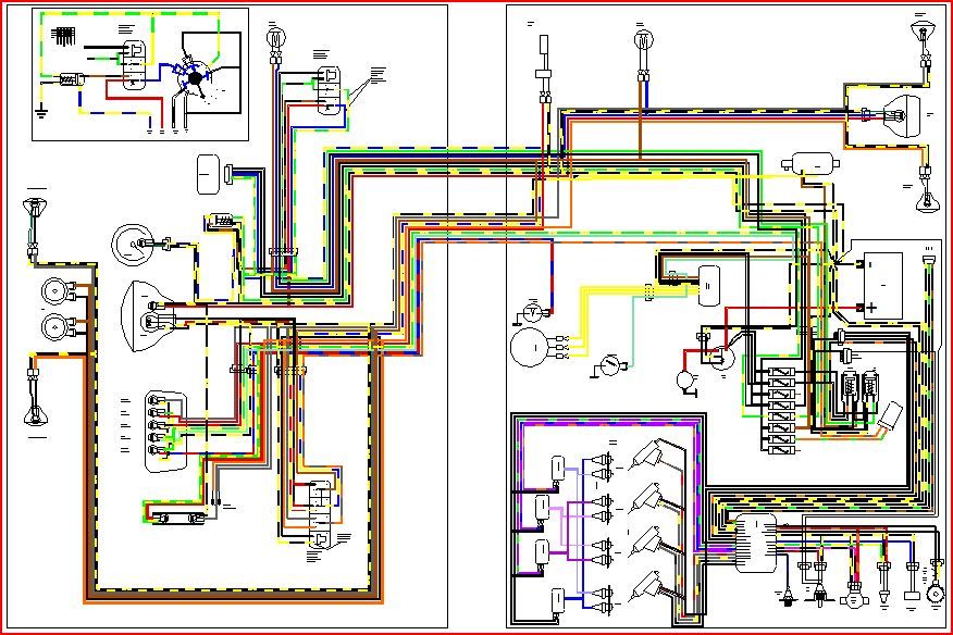
I'm going to start making a custom loom (pictured below) for my Z800 build and need to know what gauge cable to use for each part. I'm using an M-Unit to control electrics and the ring terminals are quite small on it.

Image

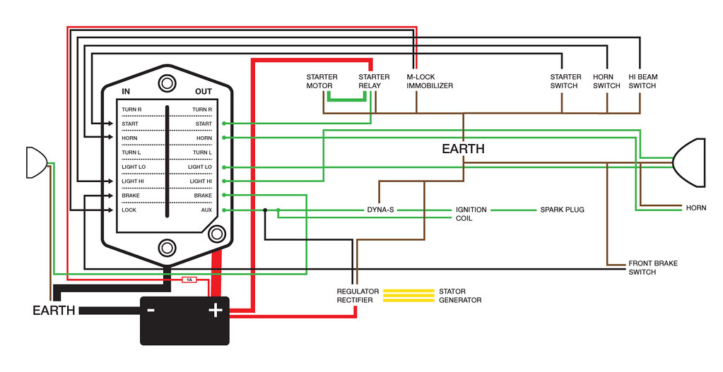
If someone could fill in the blanks as below, I'd be much obliged:

Headlamp Relay to Headlamp = 6mm / 20amp


So here is the list, grouped into sub looms:

STARTER CIRCUIT
1) Starter Switch to M-Unit =
2) Starter Switch EARTH =
3) M-Unit to Starter Relay =
4) Starter Relay to Starter Motor =
5) Battery to Starter Relay =
6) Starter Motor EARTH =
7) Starter Relay EARTH =
8) M-Lock Immobiliser = SUPPLIED
9) M-Lock Immobiliser EARTH =

LIGHTS
1) Headlamp switch to M-Unit =
2) M-Unit to Headlamp =
3) Headlamp EARTH =
4) Brake Switches to M-Unit =
5) M-Unit to Brake Light =

HORN
1) Horn Switch to M-Unit =
2) M-Unit to Horn =
3) Horn EARTH =

IGNITION CIRCUIT
1) Dyna-S = INCLUDED
2) M-Unit to Coils =
3) Reg/Rect to Coils / Dyna-S =

CHARGING
1) Reg/Rect to Battery =
2) Reg/Rect to Dyna-S =
3) Reg/Rect EARTH


Also, should all earths go to the same point on the frame or should I spread them out to shorten cable runs?

Many thanks in advance…

Rich
Hardcore
Hardcore
Posts: 2835
Joined: 4th Mar 2003

#2 PostAuthor: Rich » Wed Dec 14, 2011 5:38 pm

http://www.the12volt.com/ohm/ohmslawcalculators.asp

http://www.rowand.net/Shop/Tech/WireCapacityChart.htm

don't forget to calculate voltage drop along the wire length as well, smaller diameter wire = bigger V drop.

http://www.vehicle-wiring-products.eu/V ... dcable.php

http://www.vehicle-wiring-products.eu/V ... inwall.php

Just because a cable is the same X sectional area does not mean that it will carry the same current.
As you will see when you start to work it out your headlight cable does not need to be 6mm2.
If the cable needs to flex you are better going for more strands at smaller strand diameter which will cope with the flexing better than larger diameter strands

You need to find out what your "M unit" actually does, if it is a switching station for higher current loads the trigger wires from the switches will probably be much smaller than the feed wires to the separate functions.

http://www.vehicle-wiring-products.eu/V ... ycable.php

Personally I use 16mm2 welding cable for the starter motor and main earth, it is highly flexible and the sheathing is heat resistant.

Run your -ve (earth) back through the loom and attach spurs to different parts of the bike as well as the components - engine - frame - headlight shell, do not rely on the frame solely to conduct the current.

You may be better off having Ferret wire it up for you.
Rich
diplomacy is a form of art - I was never any good at art

User avatar
ruffle
Custard Cream
Custard Cream
Posts: 507
Joined: 29th Nov 2009
Location: Peatboghorror
Contact:

#3 PostAuthor: ruffle » Wed Dec 14, 2011 6:59 pm

Rich wrote:Personally I use 16mm2 welding cable for the starter motor and main earth, it is highly flexible and the sheathing is heat resistant.


100% agree with that - My MkIII Notrun Commando would, like all of them, hardly ever start 'on the button'. Replaced the silly little OEM wires with this stuff and she starts on the button 99% of the time :)

Also.... you don't seem to have a rear brake light switch in your diagram; can you get through an MOT without one?

Royalratch
100Club
100Club
Posts: 366
Joined: 3rd Jul 2009
Location: London

#4 PostAuthor: Royalratch » Wed Dec 14, 2011 11:36 pm

Thanks for the useful stuff guys.

I don't think you need two brake switches - just one.

So its not just a case of using wire that matches or exceeds the load of the circuit? For example, if there is significant voltage drop on a cable rated at 20amp for a component rated at 18amp then I should use a thicker cable to reduce resistance.

Sorta thing.

I've already ordered all the bits I need for the loom but hopefully I won't need to create new earth points as the loom will be much simplified.

Found this in the manual...

Image

User avatar
ruffle
Custard Cream
Custard Cream
Posts: 507
Joined: 29th Nov 2009
Location: Peatboghorror
Contact:

#5 PostAuthor: ruffle » Thu Dec 15, 2011 6:03 pm

I'd check on that brake light switch issue.

Here's the text from http://www.motuk.com/bike/1-3.asp#Menu_Top

Stop lamps may operate in conjunction with either the front or the rear brake, or both. On machines first used on or after 1 April 1986, the stop lamps must operate by the application of each system.


From the diagram of the M-unit, all the inputs are using naff all current (as one would expect as it's solid state) so you can use thin weedy cable. Have a look at a modern loom - all the stuff going to the ECU is very thin compared to 1970/80's wiring.

Rich
Hardcore
Hardcore
Posts: 2835
Joined: 4th Mar 2003

#6 PostAuthor: Rich » Thu Dec 15, 2011 6:27 pm

Looks a bit over wired to me and maybe sized for a car. Does the start circuit also run the ignition?

W/V = A

Headlights 65w / 12v = 5.5A

brake light 21w / 12v = 1.75A

If you run LEDs for the rear / idiot lights as I do then even less.

You really need to sit down with a calculator and work out what you are running and the current needed. As it seems to be a relay (transistor?) switching block I wouldn't worry too much about voltage drop as I expect most components will be direct wired and near to it. Make sure the current rating for the cable is equal too or more than the requirement. and I would beef up the alternator / rectifier to battery cables a bit.

Switches etc are running low amp and only need to trigger the relay. Does it have a breaker system for overload?

Look at your circuit, what is triggering the relay unit? Should it be positive in or do the "IN" terminals have to be earthed to switch the OUT on? Check the wiring diagram for the unit, to me the 0.01A in means that it is a positive input, your inputs are connected to the earth (-ve) in your wiring diagram.
Rich
diplomacy is a form of art - I was never any good at art

Royalratch
100Club
100Club
Posts: 366
Joined: 3rd Jul 2009
Location: London

#7 PostAuthor: Royalratch » Thu Dec 15, 2011 10:36 pm

Cheers guys.

@Rich - what do you mean over-wired and sized for a car? The diagram is just for me to understand the circuit - nothing else really.


The M-Unit is a microprocessor-controlled switching station with protection and fault display. Inputs are minimal current as stated and triggers are not connected via earth - my diagram shows Black input wire to M-Unit and triggers themselves are earthed in Brown as normal. Then M-Unit +12V out in Green to all the loads.


Brake Switch - The bike will be a 1983 so 1 brake switch will be okay it seems. Rear light will be an LED but have original also, see what it looks like.

User avatar
j.wilson
100Club
100Club
Posts: 229
Joined: 23rd Jul 2011
Location: wimborne

#8 PostAuthor: j.wilson » Fri Dec 16, 2011 8:16 am

I used 1 and 2 mm sq cables for my bike- except the main cables to the ig sw and of course the starter, engine earth and charging circiuts.

I took all my earths to a single point- if there is a problem with earth it all traces to a single point- I didnt want to be hunting about for various earth points.

Connections are where the greatest risk is (corrosion etc). All external conns should be waterproof.

After that the biggest issue for me was simple mechanics of the loom- bend rads, connector sizes, strain relief etc.
z650/1400 bonneville hybrid.

User avatar
j.wilson
100Club
100Club
Posts: 229
Joined: 23rd Jul 2011
Location: wimborne

#9 PostAuthor: j.wilson » Fri Dec 16, 2011 8:38 am

Wow- yourwiring loom is so simple compared to mine! Perhaps I need to think again in future!

Image
z650/1400 bonneville hybrid.

Crofty
ZedHead
ZedHead
Posts: 1150
Joined: 18th Nov 2009
Location: York

#10 PostAuthor: Crofty » Fri Dec 16, 2011 9:40 am

I am one of the worlds worst electricians, but where is the taillamp wiring for nighttime riding?
It has front brake only. Certain you need to have brake light for front and rear and there needs to be a wire coming from headlamp switch for low beam. I might be wrong, coz as I said I leave this stuff to experts.

Royalratch
100Club
100Club
Posts: 366
Joined: 3rd Jul 2009
Location: London

#11 PostAuthor: Royalratch » Fri Dec 16, 2011 9:44 am

Crofty wrote:I am one of the worlds worst electricians, but where is the taillamp wiring for nighttime riding?
It has front brake only. Certain you need to have brake light for front and rear and there needs to be a wire coming from headlamp switch for low beam. I might be wrong, coz as I said I leave this stuff to experts.


You're right Crofty but this is not so with an M-Unit. It's set up from factory to have the headlamp always on (but only after engine has started so doesn't draw current whilst cranking) and then the headlamp in switch triggers hi-beam. It's a digital switching station but with a few smart tricks.

As for rear light, a single wire powers both brake light and rear light and you can also choose various flashing patterns for when braking.

Crofty
ZedHead
ZedHead
Posts: 1150
Joined: 18th Nov 2009
Location: York

#12 PostAuthor: Crofty » Fri Dec 16, 2011 10:09 am

So do you just have a single filament bulb that is supplied with different current to make it glow brighter when braking?

Royalratch
100Club
100Club
Posts: 366
Joined: 3rd Jul 2009
Location: London

#13 PostAuthor: Royalratch » Fri Dec 16, 2011 12:09 pm

I'm using an LED light so its digitally controlled. The M-Unit can send pulsed current of varying speeds - always on for rear lamp but when braking is triggered it flashes the less on and off rapidly.

HowieD
100Club
100Club
Posts: 336
Joined: 5th Feb 2008
Location: Lincoln

#14 PostAuthor: HowieD » Fri Dec 16, 2011 5:16 pm

Royalratch,

you inspired me to use one of these units on mine and to that end I use the smallest signal cable for the inputs as all the needs at the switch end is a connection to earth. Mine is connected using a length of CAT5 Network cable !!

Once I finalise it all; it'll be tided up with weather proof network connectors.

regards
H
CD185, Maggot, Z1-R, Horace

Rich
Hardcore
Hardcore
Posts: 2835
Joined: 4th Mar 2003

#15 PostAuthor: Rich » Fri Dec 16, 2011 6:00 pm

Royalratch wrote:Cheers guys.

@Rich - what do you mean over-wired and sized for a car? The diagram is just for me to understand the circuit - nothing else really.


The M-Unit is a microprocessor-controlled switching station with protection and fault display. Inputs are minimal current as stated and triggers are not connected via earth - my diagram shows Black input wire to M-Unit and triggers themselves are earthed in Brown as normal. Then M-Unit +12V out in Green to all the loads.


.


So that's what threw me. Kawasaki use black/yellow for earth colours, brown is switched feed and your main earth to the battery is black. Start out 4mm2 30A - you don't need that to operate the starter solenoid. Sit down with a calculator and work out what current the cables actually need to take. As Howie says you can use data cable for the feeds.

I use an Led rear light that is controlled by a twin resistor network, a couple of diodes to stop reverse feeds and run 4 leds in series. Higher resistance for rear light, less resistance for brake.
Rich
diplomacy is a form of art - I was never any good at art


Return to “Bike Help”

Who is online

Users browsing this forum: No registered users and 16 guests