Page 1 of 1
combined rectifier/regulator
Posted: Wed Jan 20, 2010 7:29 pm
Author: bunnysZ
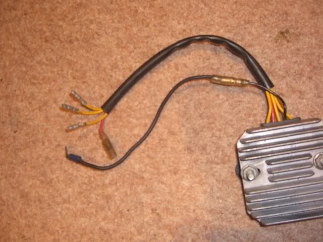
i have one of these combined reg/rec
can anyone tell me (or post pics) where the wires go...
it has 3 yellows with bullet male connections 1 red with female connection
and a black wire on it .
Posted: Wed Jan 20, 2010 8:58 pm
Author: KeithZ1R
May be talkin Bollox here (not an unusual situation) but you appear to be missing the heavy DC output wire what make is it ?
three ac inputs (yellow)one ground (black) one voltage sense (red) and usually another heavy red wire
Maybe somebody else recognises it
Posted: Wed Jan 20, 2010 9:11 pm
Author: PAULJAC47
Just about ready to fit mine as follows 3 yellow output from alternator ie 3 phase ac,brown is voltage sensing ie a switched positive eg from brake lamp circuit only on when ignition is on and red and white is the feed to the battery positive, black is negative(frame),On a H**** wet dream unit three yellows from alternator Black is the voltage sensing wire red to the battery green to negative (frame)hope this is some use Paul J..
Posted: Fri Jan 22, 2010 9:29 pm
Author: Garn 1
BunnysZ, I have always wondered about this set up of the combination Rectifier/ Regulator.
Some say you can only use a "6 wire" system.
3 altenator wires (usually Yellow)
1 earth (Black)
1 positive (White)
1 positive /switch (usually brown).
I have heard of your "5 wire" system being fitted and, I guess, I just can't understand the circuit where the extra wire is needed in one and not the other? The extra wire on the "6-wire" system is used on the "switch" circuit.
I have seen where, as Pauljac77 says, the "H***a wet dream unit" does work on the Zed's, however I understand, it also is a "6-wire" unit
Posted: Sun Jan 24, 2010 6:35 pm
Author: Rich
You have the wrong RR. The sixth wire (brown in Kawasakis case) is voltage sensing.
Posted: Mon Jan 25, 2010 2:28 pm
Author: 02GF74
this has puzzled me too - when I look at the Z1000 wiring diagram, the two wires eventually go to the same point.
From memroy - and this may be wrong - the sence wire goes to the battery and the main output goes to the igniton switch to power the electrics but ultimately both surel must go to the 12 V line?
I am sure this subject has been discussed on here so do a search.