Goodbye to ....
Posted: Sat Oct 17, 2009 5:49 pm
.... boiled batteries, the smell of rotten eggs and blown instrument bulbs.
If you experience any one or more of the above, you have a duff voltage regulator, seemingly a very common occurrence for all big Zed owners.
Either you fork out over £ 70 for a replacement unit or fit a regulator from another motorbike.
Well, as promised, here is how I replaced both rectifier and regulator by a voltage regulator from a Kawasaki GPz 550, bought on ebay for £ 10.
In the past, I came to the conclusion that the rectifier unit had gone so instead of paying a huge sum of money, I made my own as below.
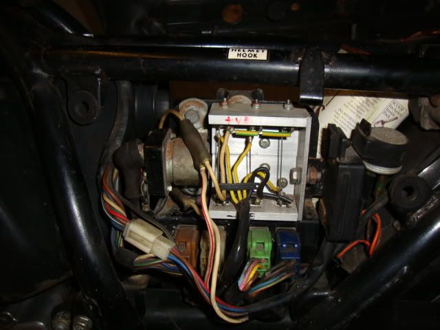
But all was not well as I had the aforementioned symptoms and when measuring the voltage across the battery at 2,000 rpm and above it was 17.3 V. Haynes states the voltage should be limited to 15-16 V so clearly the regulator was no good.
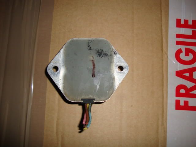
Removing the regulator, it is clear there has been some damage as the epoxy insulation has bulged and some nasty brown gunge has dribbled out of the unit! No amount of toilet paper will fix that.
The Zed voltage regulator sits on the opposite side and ideally to avoid long wires, it would be best to fit the combined unit here but that is not possible if the fins are to be kept horizontal for optimal cooling.
First thing I did was to check the wiring - the white and green sockets are wired up in parallel so it does not matter which is used, I chose to use the green socket since this had the long wires to the voltage regulator. The white plug has black lead - 0 V - connected but not the green so the first step was to remove that wire. This is done by using two very thin screwdrivers, we're talking 1 mm, to push two tabs for the pin to be released, and then pushed into the green connector.
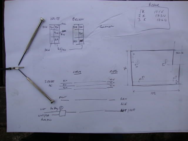
I used a Kawasaki GPz 550 regulator but the holes are in different positions, so an adapter plate from 3 mm aluminium (best for conducting heat) was made, the dimensions and positions of the holes is shown above. It was painted matt black.
The wires are as follows:
Zed loom ---------- regulator
brown ------------ brown regulated 12 V
black ------------- black 0 V
pink --------------- yellow these are outputs from generator
blue ------------- yellow
yellow ------------- yellow
white/red ------- white/red 12 V to battery
The pink/blue/yellow are interchangeable so can be connected to any of the regulator's yellow wires.
The Zed has a 3 way connector with two white/red wires and one white wire, the latter going to the battery positive terminal.
I fitted a 3 way connector to connect the black wire from the voltage regulator to the black/yellow wire in the green socket and a black/yellow wire from the loom- I am pretty sure connecting to the wire from the loom is not necessary - I checked with multimeter it was common, but I connected it anyway just to rule out any problems. I can always unplug it and see what effect it has.
Joining the wires was very time consuming. About 12 mm of insulation is stripped off and the wires cleaned by rubbing with some wet'n'dry until shiny. Then the wires are splayed into a fan shape, pushed together and twisted over each other. It is important for wires to have good contact prior to soldering.
To keep the strands in place, I wrapped a single thin copper wire strand around both ends, applied some flux then soldered together. A piece of heatshrink slid over the join - oh yeah, make sure you put that on before soldering the wires. Finally the plastic cover having been previously slit, placed over the wires and some black insulation tape to hold it all in place.
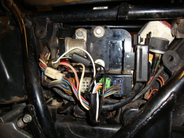
GPZ 550 regulator fitted
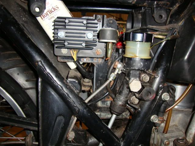
I ran the engine and the measured voltage across the battery. It does not go over 15.0 V, and when the headlamp is on, 15.5 V. Much better.
If you experience any one or more of the above, you have a duff voltage regulator, seemingly a very common occurrence for all big Zed owners.
Either you fork out over £ 70 for a replacement unit or fit a regulator from another motorbike.
Well, as promised, here is how I replaced both rectifier and regulator by a voltage regulator from a Kawasaki GPz 550, bought on ebay for £ 10.
In the past, I came to the conclusion that the rectifier unit had gone so instead of paying a huge sum of money, I made my own as below.
But all was not well as I had the aforementioned symptoms and when measuring the voltage across the battery at 2,000 rpm and above it was 17.3 V. Haynes states the voltage should be limited to 15-16 V so clearly the regulator was no good.
Removing the regulator, it is clear there has been some damage as the epoxy insulation has bulged and some nasty brown gunge has dribbled out of the unit!
The Zed voltage regulator sits on the opposite side and ideally to avoid long wires, it would be best to fit the combined unit here but that is not possible if the fins are to be kept horizontal for optimal cooling.
First thing I did was to check the wiring - the white and green sockets are wired up in parallel so it does not matter which is used, I chose to use the green socket since this had the long wires to the voltage regulator. The white plug has black lead - 0 V - connected but not the green so the first step was to remove that wire. This is done by using two very thin screwdrivers, we're talking 1 mm, to push two tabs for the pin to be released, and then pushed into the green connector.
I used a Kawasaki GPz 550 regulator but the holes are in different positions, so an adapter plate from 3 mm aluminium (best for conducting heat) was made, the dimensions and positions of the holes is shown above. It was painted matt black.
The wires are as follows:
Zed loom ---------- regulator
brown ------------ brown regulated 12 V
black ------------- black 0 V
pink --------------- yellow these are outputs from generator
blue ------------- yellow
yellow ------------- yellow
white/red ------- white/red 12 V to battery
The pink/blue/yellow are interchangeable so can be connected to any of the regulator's yellow wires.
The Zed has a 3 way connector with two white/red wires and one white wire, the latter going to the battery positive terminal.
I fitted a 3 way connector to connect the black wire from the voltage regulator to the black/yellow wire in the green socket and a black/yellow wire from the loom- I am pretty sure connecting to the wire from the loom is not necessary - I checked with multimeter it was common, but I connected it anyway just to rule out any problems. I can always unplug it and see what effect it has.
Joining the wires was very time consuming. About 12 mm of insulation is stripped off and the wires cleaned by rubbing with some wet'n'dry until shiny. Then the wires are splayed into a fan shape, pushed together and twisted over each other. It is important for wires to have good contact prior to soldering.
To keep the strands in place, I wrapped a single thin copper wire strand around both ends, applied some flux then soldered together. A piece of heatshrink slid over the join - oh yeah, make sure you put that on before soldering the wires. Finally the plastic cover having been previously slit, placed over the wires and some black insulation tape to hold it all in place.
GPZ 550 regulator fitted
I ran the engine and the measured voltage across the battery. It does not go over 15.0 V, and when the headlamp is on, 15.5 V. Much better.