Hello Guest User,

Please feel free to have a look around the forum but be aware that as an unregistered guest you can't see all of it and you can't post.

To access these 'Registered Users Only' areas simply register and login.

combined rectifier/regulator

Need help restoring, building, or finding then try here.

Moderators: KeithZ1R, chrisu, paul doran, Taffus

Message
Author
User avatar
bunnysZ
Granny Magnet
Posts: 1576
Joined: 7th Mar 2006
Location: herts

combined rectifier/regulator

#1 PostAuthor: bunnysZ » Wed Jan 20, 2010 7:29 pm

i have one of these combined reg/rec
can anyone tell me (or post pics) where the wires go...
it has 3 yellows with bullet male connections 1 red with female connection
and a black wire on it .
Image
zed the best ride of your life ...... so far

User avatar
KeithZ1R
Moderator
Posts: 3368
Joined: 15th May 2005
Location: Bury

#2 PostAuthor: KeithZ1R » Wed Jan 20, 2010 8:58 pm

May be talkin Bollox here (not an unusual situation) but you appear to be missing the heavy DC output wire what make is it ?

three ac inputs (yellow)one ground (black) one voltage sense (red) and usually another heavy red wire

Maybe somebody else recognises it
Keith
:bop :gom

You can never have too many tools in your life, except the two legged variety

I'm never wrong, once I thought I was but I was
mistaken.

Phil Churchett winner 2013

User avatar
PAULJAC47
Hardcore
Hardcore
Posts: 3266
Joined: 31st Aug 2008
Location: WOLVO WEST MIDS ENGLAND

#3 PostAuthor: PAULJAC47 » Wed Jan 20, 2010 9:11 pm

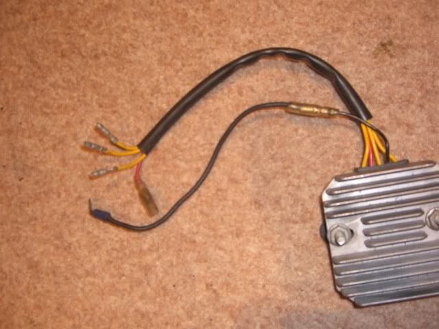
Just about ready to fit mine as follows 3 yellow output from alternator ie 3 phase ac,brown is voltage sensing ie a switched positive eg from brake lamp circuit only on when ignition is on and red and white is the feed to the battery positive, black is negative(frame),On a H**** wet dream unit three yellows from alternator Black is the voltage sensing wire red to the battery green to negative (frame)hope this is some use Paul J..
PAULJAC47,,,,,"She may not look like much, but she's got it where it counts, kid."
-Han Solo

You can't polish a turd, but you can roll it in glitter

Salad is what real food eats.
Anon

PUM 673

User avatar
Garn 1
ZedHead
ZedHead
Posts: 1234
Joined: 23rd Sep 2005
Location: Sydney

#4 PostAuthor: Garn 1 » Fri Jan 22, 2010 9:29 pm

BunnysZ, I have always wondered about this set up of the combination Rectifier/ Regulator.
Some say you can only use a "6 wire" system.
3 altenator wires (usually Yellow)
1 earth (Black)
1 positive (White)
1 positive /switch (usually brown).

I have heard of your "5 wire" system being fitted and, I guess, I just can't understand the circuit where the extra wire is needed in one and not the other? The extra wire on the "6-wire" system is used on the "switch" circuit.

I have seen where, as Pauljac77 says, the "H***a wet dream unit" does work on the Zed's, however I understand, it also is a "6-wire" unit
Garn (Sydney) Z1, Z1A, Z1B and Z900-A4

Rich
Hardcore
Hardcore
Posts: 2835
Joined: 4th Mar 2003

#5 PostAuthor: Rich » Sun Jan 24, 2010 6:35 pm

You have the wrong RR. The sixth wire (brown in Kawasakis case) is voltage sensing.
Rich
diplomacy is a form of art - I was never any good at art

User avatar
02GF74
100Club
100Club
Posts: 334
Joined: 31st Mar 2008
Location: South Herts

#6 PostAuthor: 02GF74 » Mon Jan 25, 2010 2:28 pm

this has puzzled me too - when I look at the Z1000 wiring diagram, the two wires eventually go to the same point.

From memroy - and this may be wrong - the sence wire goes to the battery and the main output goes to the igniton switch to power the electrics but ultimately both surel must go to the 12 V line?

I am sure this subject has been discussed on here so do a search.


Return to “Bike Help”

Who is online

Users browsing this forum: No registered users and 13 guests