

Had a set of those Richmond walldrive sockets and spanners for around twenty odd years now.
Worth their weight in gold.
Got them at a discount with a subscription of Mechanics magazine.
Didn't expect them to still be like new after all this time.
Quality gear.
Hello Guest User,
Please feel free to have a look around the forum but be aware that as an unregistered guest you can't see all of it and you can't post.
To access these 'Registered Users Only' areas simply register and login.
Please feel free to have a look around the forum but be aware that as an unregistered guest you can't see all of it and you can't post.
To access these 'Registered Users Only' areas simply register and login.
Building my bike workshop
Moderators: KeithZ1R, chrisu, paul doran, Taffus


So, back to my story of the router table.
I’ve got my T track fitted and I need to fit the router mount plate.
Router tools are very expensive but I have a set I got for £40 and went thru these to see what I could use.
One of the main problems was to match the corner rads of the router mount plate and the corners that I had tools to make.
Eventually I struck a combination and I set to work making the jig to make the tool to make the hole.
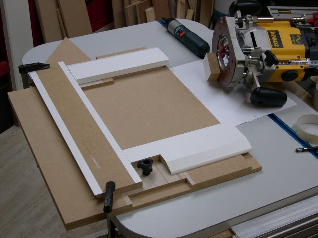
So here is the jig.
I set two fences up on a sheet of MDF to make a right angle (I used the router plate to form this right angle. I then attached the third fence, but this one I fitted as a sliding fence. Simply it was another piece of mdf set in a gap between two others. I routed a slot in it and fitted a thumb nut to hold it in place.
I did this so I could adjust the width of the cut to fit exactly the router plate.
Stuck to the top of the jig you can see the 15mm mdf Iam using to make the template tool.
I’m sure you recognise this as skirting board- but it was the cheapest form of 15mm mdf I could find in B&Q.
I used a router bit to rout the shape of each side of the router plate using the jig as a guide.
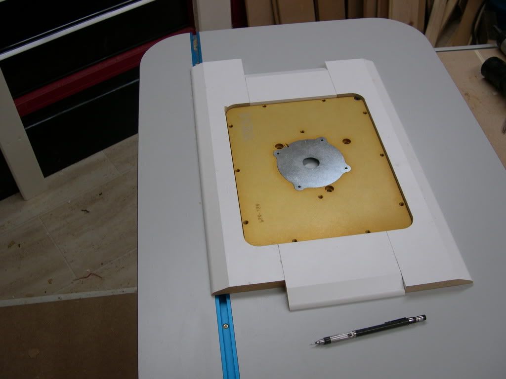
As the skirting board template pieces were the same size as the real router plate I could try the plate in position and adjust the jig till the plate fitted nicely in the machined rebate.
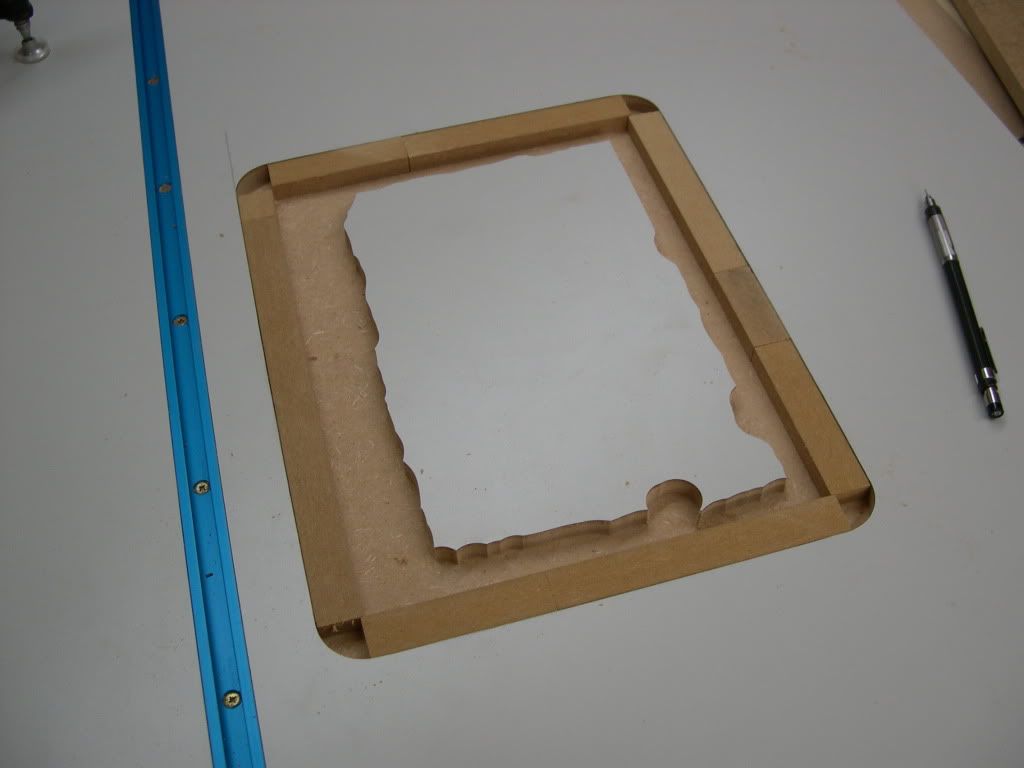
Once I got this set I took it apart and used some wood filler in the corner of the jig to make a rad in its square corners. I used a suitable router bit to form a perfect rad in the filler then I cut the template bits for real.
Here the bits are cut and form a neat nest for the router plate.
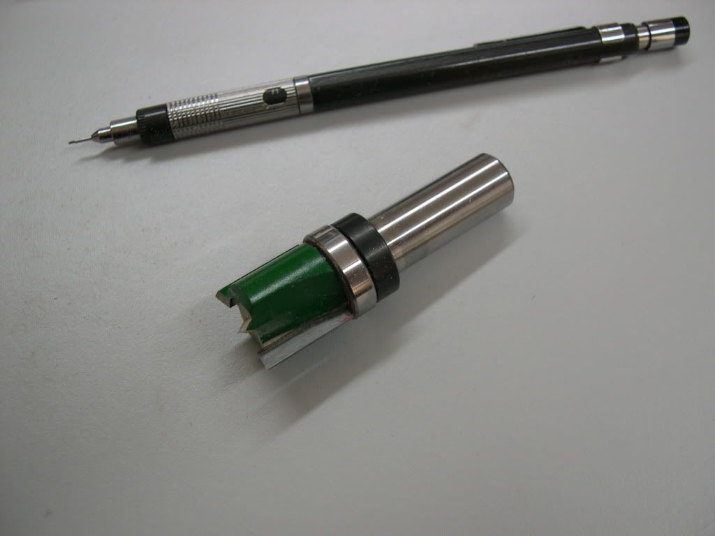
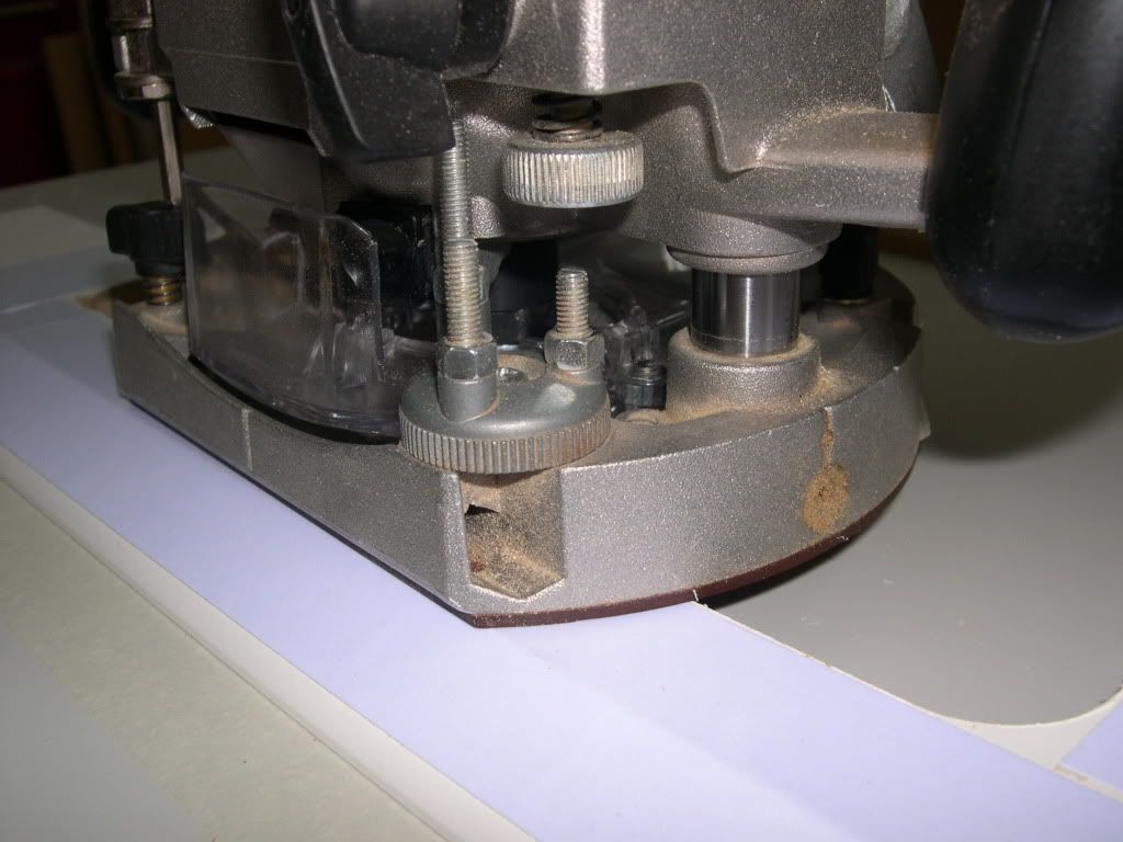
This little tool here cost me £20, and I used to cut the rebate in the table. It has a bearing above it to follow the sides of my template.
Here I’m putting masking tape onto the table surface so that when I stick the template bits down with double sided, I can get them off again after.
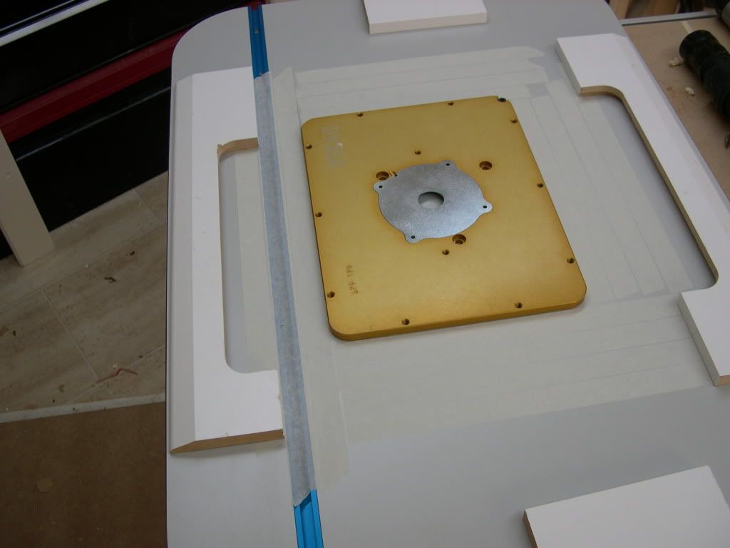
Ready to route. I put the router in place and wound it down till the tool kissed the surface of the table.
I set the depth of the router by putting the router plate between the adjustable depth stop and squeezing it tight.
I should note here that I stuck a bit of material the same thickness as the template on the bottom of the router so that it had support both sides of the cut. It is a common mistake not to do this and its very difficult to keep the router steady when making a cut without it.
So, now the moment of no return.
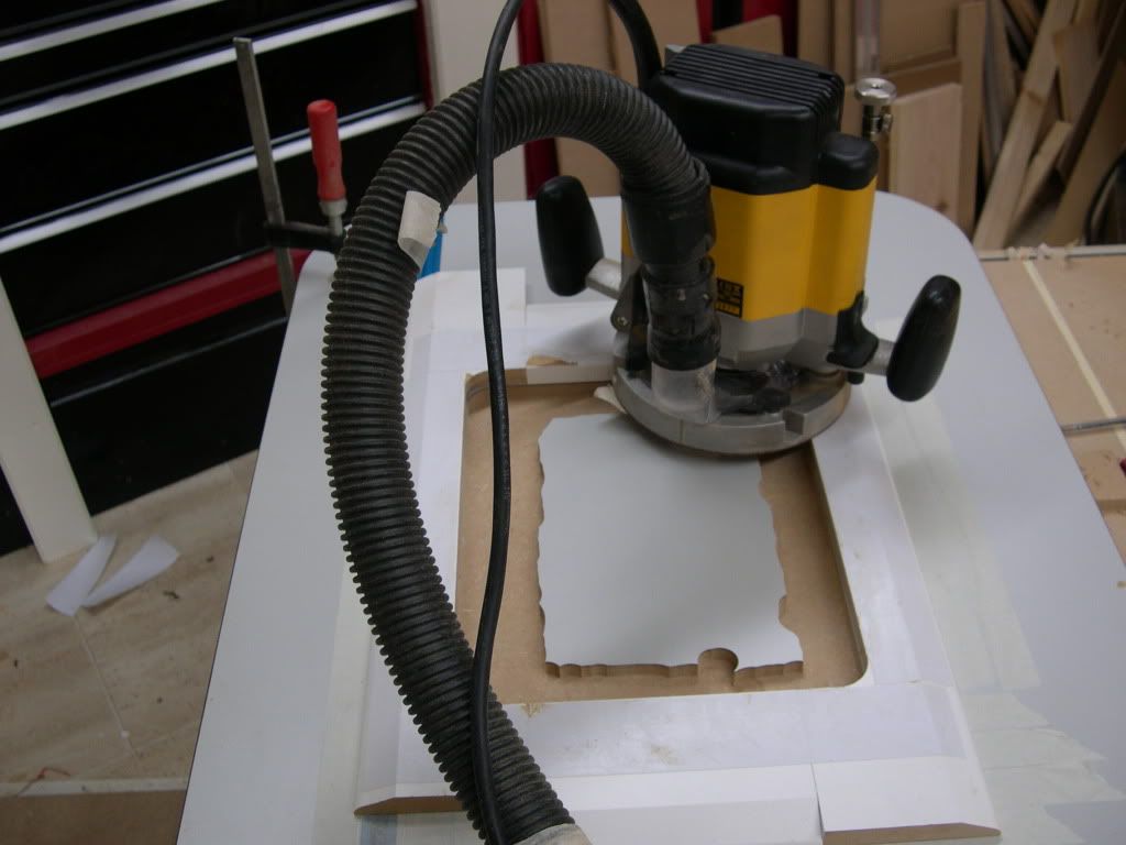
To cut the thru hole, I stuck some mdf the width of the ledge I wanted around the side of the rebate.
Then I used the same tool to simply cut right thru.
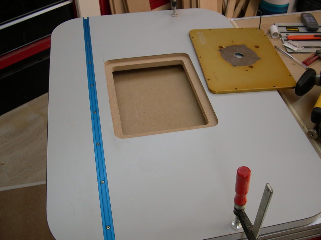
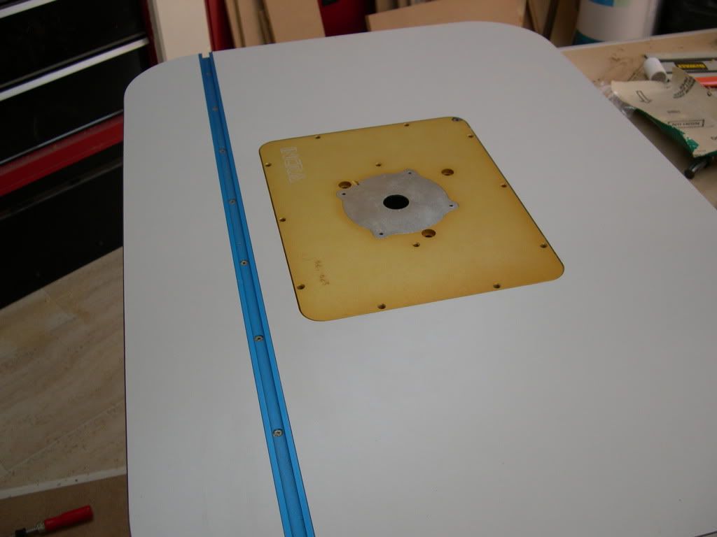
Voila – and it fits!
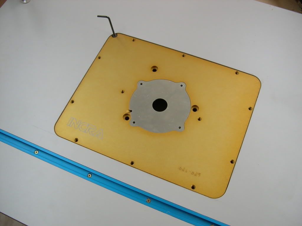
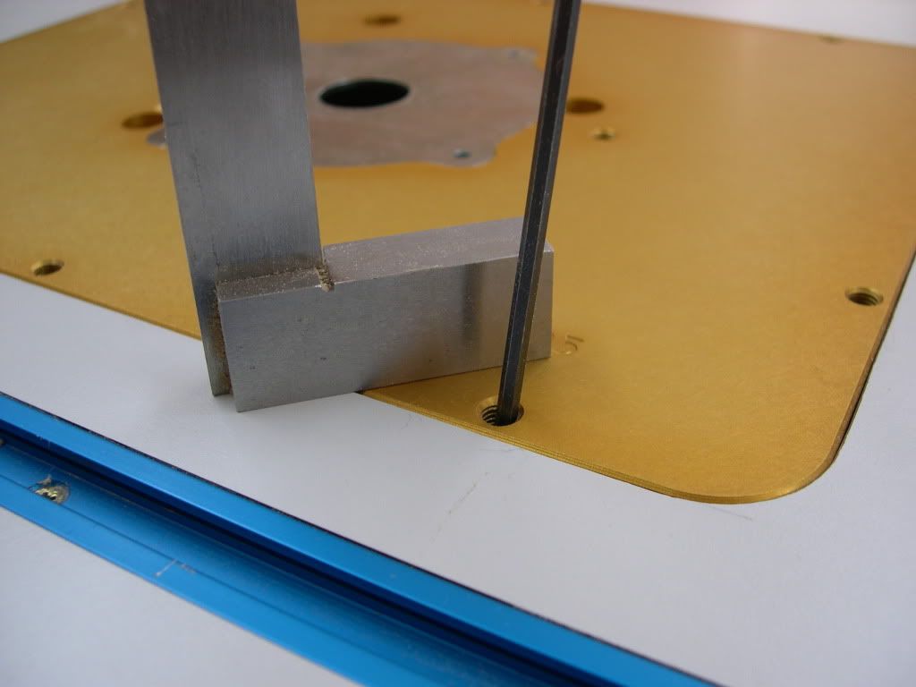
I used the plate in position to spot drill the adjuster holes. I drilled them and tapped them at least half way thru.
I’ve got my T track fitted and I need to fit the router mount plate.
Router tools are very expensive but I have a set I got for £40 and went thru these to see what I could use.
One of the main problems was to match the corner rads of the router mount plate and the corners that I had tools to make.
Eventually I struck a combination and I set to work making the jig to make the tool to make the hole.
So here is the jig.
I set two fences up on a sheet of MDF to make a right angle (I used the router plate to form this right angle. I then attached the third fence, but this one I fitted as a sliding fence. Simply it was another piece of mdf set in a gap between two others. I routed a slot in it and fitted a thumb nut to hold it in place.
I did this so I could adjust the width of the cut to fit exactly the router plate.
Stuck to the top of the jig you can see the 15mm mdf Iam using to make the template tool.
I’m sure you recognise this as skirting board- but it was the cheapest form of 15mm mdf I could find in B&Q.
I used a router bit to rout the shape of each side of the router plate using the jig as a guide.
As the skirting board template pieces were the same size as the real router plate I could try the plate in position and adjust the jig till the plate fitted nicely in the machined rebate.
Once I got this set I took it apart and used some wood filler in the corner of the jig to make a rad in its square corners. I used a suitable router bit to form a perfect rad in the filler then I cut the template bits for real.
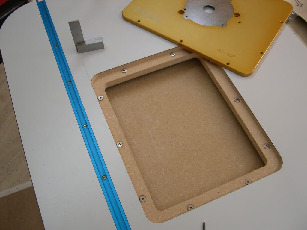
Here the bits are cut and form a neat nest for the router plate.
This little tool here cost me £20, and I used to cut the rebate in the table. It has a bearing above it to follow the sides of my template.
Here I’m putting masking tape onto the table surface so that when I stick the template bits down with double sided, I can get them off again after.
Ready to route. I put the router in place and wound it down till the tool kissed the surface of the table.
I set the depth of the router by putting the router plate between the adjustable depth stop and squeezing it tight.
I should note here that I stuck a bit of material the same thickness as the template on the bottom of the router so that it had support both sides of the cut. It is a common mistake not to do this and its very difficult to keep the router steady when making a cut without it.
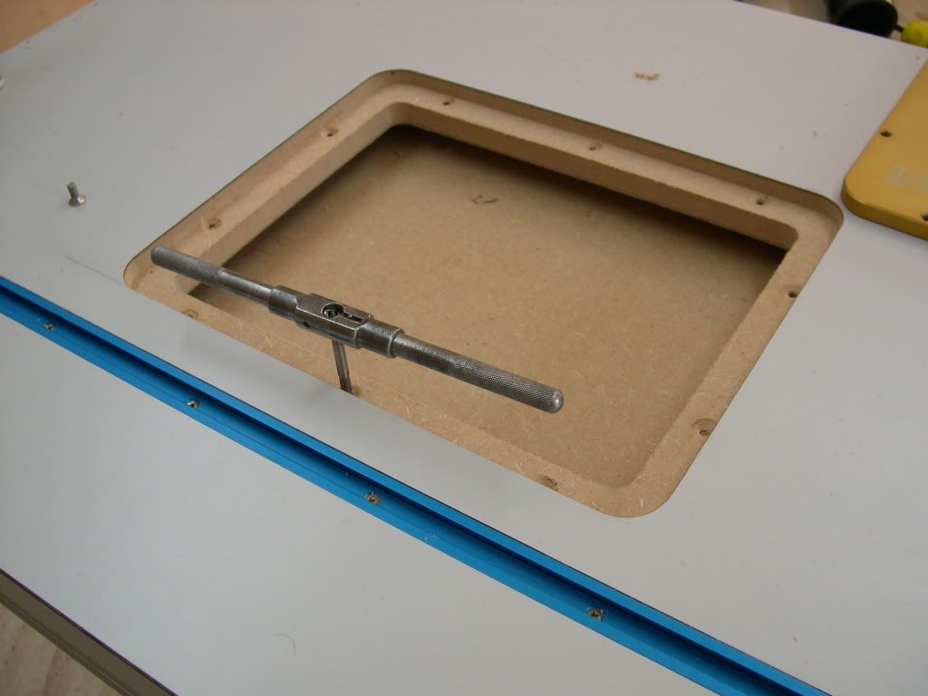
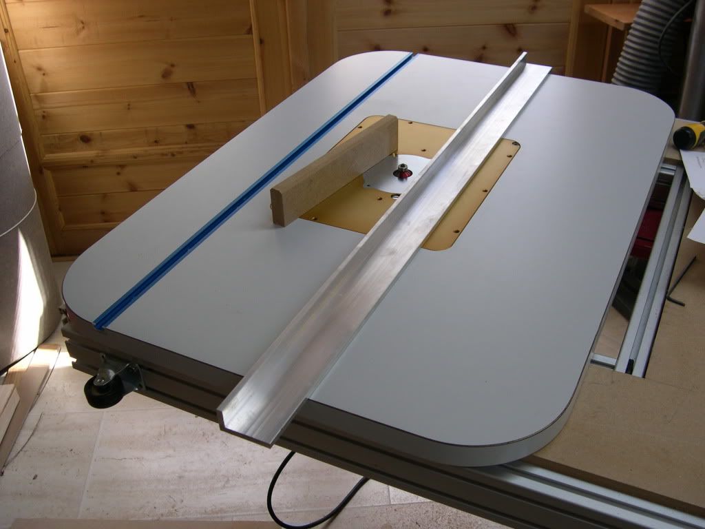
So, now the moment of no return.
To cut the thru hole, I stuck some mdf the width of the ledge I wanted around the side of the rebate.
Then I used the same tool to simply cut right thru.
Voila – and it fits!
I used the plate in position to spot drill the adjuster holes. I drilled them and tapped them at least half way thru.
z650/1400 bonneville hybrid.
Who is online
Users browsing this forum: No registered users and 8 guests